#Arduino Uno At-mega
Explore tagged Tumblr posts
Visit Tumblr Blog
Explore Tumblr blogs with no restrictions, modern design and the best experience.
Last Seen Tumblr Blogs


Fun Fact
Women make up for the other 50% of Tumblr’s audience.
Text

Chengsuchuang Ultrasonic Module Robotica Kit for Arduino STEM The Robotica Kit detaction specification as below: - Detection Range:0-180° - Detection Distance:10-300CM Size of the ultrasonic module robotica kit: Introduction of this stem education robotic kit: This ultrasonic module robotica kit designed based on an ultrasonic module to calculate ultrasonic waves, and calculates the length of time it takes to retract the waveform to get the distance of the object in front. The servo can be positioned at any angle within 0-180°, and the servo is equipped with an ultrasonic module to detect the distance of objects within 180 degrees around it. The output measurement results can be displayed on the lcd module and presented in a graphical manner. Note:We only provide hardware.Turtial or lesson is not provided,they are universal use everywhere from the internet. If you also interested with other development kits,view here.If you are STEM education user,welcome contact us to talk the customzied hardware list. About Us: Shenzhen Chengsuchuang Technology Co.,Ltd. provide one stop supply solution to Arduino development board kits,including arduino uno,mega,nano etc.All of our products warranty is 1 year warranty default.We are in the electronics hardware since 2014. Read the full article
0 notes
Text
Grafische Programmierung mit Open Roberta

In diesem Beitrag möchte ich dir zeigen, wie du mit der grafischen Programmierung in Open Roberta startest.

Die grafische Programmierung für Mikrocontroller habe ich dir bereits mit der Anwendung ArduBlock und MakeCode gezeigt.
Was ist Open Roberta?
Das Open Roberta Lab ist eine kostenfreie Open-Source-Plattform vom Fraunhofer-Institut. Die Zielgruppe von Open Roberta sind Lehrkräfte, Schüler, Azubis und Studierende. Dieses wird möglich, da die Software technische und fachliche Barrieren durch einfache und intuitive Bedienung ersetzt hat. Wenn du mehr darüber lesen möchtest, dann empfehle ich dir den Wikipedia Artikel dazu. Seite „Open Roberta“. In: Wikipedia – Die freie Enzyklopädie. Bearbeitungsstand: 5. Januar 2023, 09:36 UTC. URL: https://de.wikipedia.org/w/index.php?title=Open_Roberta&oldid=229508414 (Abgerufen: 17. März 2023, 11:03 UTC)
Was benötige ich zur Programmierung in Open Roberta?
Du benötigst einen Computer oder Tablet sowie ein USB-Datenkabel. Für die Entwicklung am Tablet benötigst du ein OTG Datenkabel, welches du zum Beispiel auf ebay.de für wenige Euro* findest. Hinweis von mir: Die mit einem Sternchen (*) markierten Links sind Affiliate-Links. Wenn du über diese Links einkaufst, erhalte ich eine kleine Provision, die dazu beiträgt, diesen Blog zu unterstützen. Der Preis für dich bleibt dabei unverändert. Vielen Dank für deine Unterstützung!

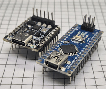
OTG Kabel für die serielle Verbindung zu einem Mikrocontroller Du kannst mit dieser Entwicklungsumgebung diverse Mikrocontroller programmieren. In diesem und nachfolgende Beiträge zeige ich dir die Entwicklung am Arduino UNO. Diesen Mikrocontroller kannst du entweder direkt im Onlineshop bei Arduino bestellen oder auch als günstigen "China Klone" schon ab 5 € auf ebay.de*.

originaler Arduino UNO

Arduino UNO als China Klone

Arduino UNO von Keyestudio Eine günstige Alternative zum originalen Arduino UNO habe ich dir im Beitrag Review Funduino UNO vorgestellt. Dieser ist, wie ich finde, dem originalen schon sehr nahe.

Original Arduino UNO & Funduino UNO
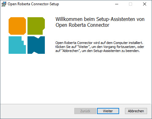
Installieren des Open Roberta Connectors
Damit du später deinen Arduino aus Open Roberta programmieren bzw. ein Programm auf diesen spielen kannst benötigst du den Open Roberta Connecotor welchen du vom GitHub Repository OpenRoberta/openroberta-connector für diverse Betriebssysteme herunterladen kannst.


Zusätzlich benötigst du noch ein installiertes Java 1.8 welches du ebenfalls kostenfrei herunterladen und installieren kannst.
Erste Schritte in Open Roberta
Wagen wir nun die ersten Schritte in Open Roberta mit dem Arduino UNO. Dazu öffnen wir als Erstes die Seite https://lab.open-roberta.org/ und wählen dort das System "Nepo4Arduino" aus.
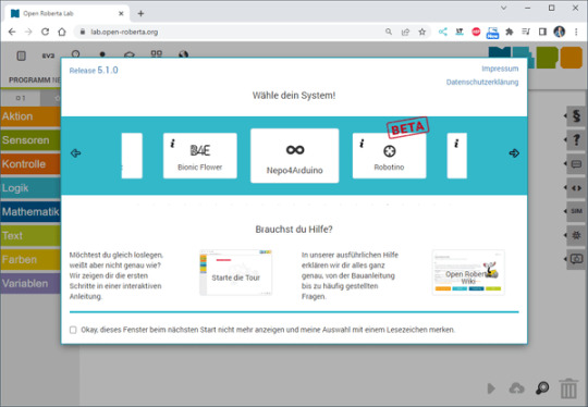
Auswahl - System "Nepo4Arduino" in Open Roberta Lab Im nächsten Schritt wählen wir den Mikrocontroller aus, derzeit unterstützt das Tool lediglich den Arduino UNO, Nano sowie den Mega.

Unterstützte Mikrocontroller der Arduino Familie im Open Roberta Lab Die Wifi Rev2 Variante ist derzeit im Status DEPRECATED und wird nicht mehr unterstützt. In meinem Fall nutze ich wie erwähnt den Arduino UNO und wähle hier "Nepo4Arduino Uno" aus.
Aufbau einer Verbindung mit einem Mikrocontroller
Wenn der Mikrocontroller an den Computer mit einem USB-Datenkabel angeschlossen wurde, dann müssen wir zunächst den zuvor installierten Open Roberta Connector starten. Dieser sucht dann automatisch nach einem Mikrocontroller und wir erhalten nach einem Klick auf die Schaltfläche "Verbinden" ein Token.


Mit der kleinen, grünen Schaltfläche neben dem Token können wir diesen in die Zwischenablagen ablegen. In der Webseite navigieren wir nun über Roboter > verbinden ... zum Dialog zur Eingabe des Tokens.

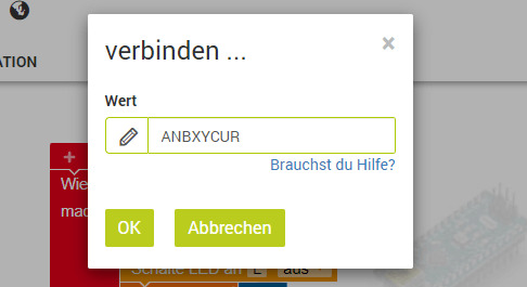
Diese Eingabe bestätigen wir mit der Schaltfläche "OK" und somit sollte im unteren Bereich die Schaltfläche zum Überspielen eines Codes aktiviert werden.

LED blinken lassen
Starten wir jetzt mit einem einfachen Programm und lassen die interne LED am digitalen Pin D13 des Mikrocontrollers blinken. Im nachfolgenden YouTube-Video erläutere ich dir, wie du eine Verbindung von deinem Computer zum Mikrocontroller aufbaust und das kleine Programm zum Blinken einer LED programmierst. https://youtu.be/VyzjWcSH3uk Wenn du bereits mit MakeCode oder ArduBlock Erfahrung gesammelt hast, dann musst du dich nicht viel umstellen, außer dass du bei der grafischen Programmierung in Open Roberta noch zusätzlich die Schaltung abbilden musst. Die Schaltung erstellst du im Reiter "ROBOTERKONFIGURATION". Hier ist als Erstes bereits eine LED konfiguriert.
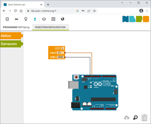
Diese LED mit der Bezeichnung "L" können wir jetzt im Code referenzieren und mit definierten Elementen zum Blinken bringen.

Read the full article
0 notes
Text
Chatgpt computer communication design
Designing a computer circuit where two computers communicate with each other and "teach themselves" using an Arduino board involves a combination of hardware setup and software programming. Here’s a general guide to get you started:
1. Basic Concept
Two Computers (PCs or Microcontrollers): These are the two devices that will communicate and learn from each other. Each will run a program for self-learning.
Arduino Board: The Arduino will facilitate the communication between the two computers and control the process. It could also be part of the system performing calculations or simulations.
Communication Protocol: The two computers will need to communicate with each other. For simplicity, we can use serial communication (UART) or I2C with the Arduino acting as the intermediary.
2. Hardware Components
Arduino Board (e.g., Arduino Uno, Nano, or Mega)
Two Computers (PCs or other microcontrollers, like Raspberry Pi or other Arduino boards)
Communication Module: If you are using something like a Raspberry Pi or another microcontroller, you might need USB-to-Serial adapters or Bluetooth/Wi-Fi modules (e.g., ESP8266/ESP32, HC-05).
Power Supply: Proper power sources for the Arduino and computers.
Cables: USB, serial cables, or jumper wires for communication.
3. Circuit Design
Here is a high-level overview of the connections between the Arduino and the two computers.
Arduino and PC1 (Computer 1):
Connect the Arduino to PC1 via USB or UART communication pins (TX/RX pins if using serial).
Arduino and PC2 (Computer 2):
If you are using a second microcontroller (like another Arduino or a Raspberry Pi), connect them to the Arduino board using a communication protocol (e.g., I2C or UART).
The two computers could either communicate directly over a network (like Ethernet or Wi-Fi) or through serial communication.
For this example, let’s assume you are using UART for communication between the Arduino and both computers. You can use the TX/RX pins on the Arduino and connect them to the USB-to-Serial adapters connected to each computer.
4. Software Design
The software should allow the computers to "teach themselves," which likely means implementing some form of machine learning or pattern recognition. For simplicity, let’s outline how you could set up communication, with the learning part handled on the computers.
Arduino Code: The Arduino will act as the middleman for the communication. It will receive data from one computer, send it to the other, and also handle basic processing or simulation. It can be programmed to send responses or instructions back to the computers.
// Simple Arduino code for UART communication void setup() { Serial.begin(9600); // Start the serial communication at 9600 baud } void loop() { if (Serial.available()) { char incomingByte = Serial.read(); // Read incoming byte Serial.print("Received: "); Serial.println(incomingByte); // Send back the received byte } }
Computer 1 and Computer 2 Code: Each computer should run a program that will send data to the Arduino and receive responses. This could be a simple Python script or C++ program for serial communication.
Example Python Script: Here’s a basic Python script that can run on each computer. This script will send data to the Arduino and read the response back.import serial import time # Open serial port (make sure to change COM port for your system) ser = serial.Serial('COM3', 9600) # Change COM port as needed time.sleep(2) # Wait for the serial connection to initialize # Send data to Arduino ser.write(b'Hello Arduino!\n') # Read response while True: if ser.in_waiting > 0: response = ser.readline().decode('utf-8').strip() print(f"Arduino says: {response}") break ser.close()
This Python script could run on Computer 1, while a similar script runs on Computer 2. Both will send messages to the Arduino and receive feedback.
5. Self-Learning Simulation
To simulate the "self-teaching" aspect, each computer can use machine learning algorithms. You could start with something simple like linear regression or a decision tree. The computers could send random data points to each other and exchange feedback on whether the predictions made by each other are correct.
Computer 1 could generate a random dataset and send it to Computer 2.
Computer 2 processes the data, makes predictions, and sends the feedback back.
Computer 1 uses this feedback to adjust its learning algorithm (e.g., adjust weights in a simple linear regression model).
Example of a Simple Learning Process: Each computer could adjust its internal model based on the received feedback, similar to how a neural network or other machine learning models learn. The Arduino could be involved in simple processing tasks or sending acknowledgment signals when certain thresholds are reached (e.g., "success" or "failure").
6. Scaling Up
If you want to scale up the project to involve more complex learning or higher levels of interaction, you could use a more advanced platform such as a Raspberry Pi or ESP32/ESP8266 for networking and faster processing, where each computer uses a machine learning library (like TensorFlow Lite or scikit-learn).
7. Final Setup
Computer 1 and Computer 2 run machine learning algorithms that adjust based on feedback.
Arduino manages data flow between the computers and possibly performs basic learning tasks like adjusting variables or sending commands.
The entire system simulates a network where two computers are learning from each other.
This is a high-level overview, and there are many ways to implement it depending on the complexity of the communication and learning algorithm you want to achieve. Would you like to dive deeper into any specific area or need more detailed code for the project?
Creating two PCs from scratch using Arduino boards is an interesting challenge, but it's important to note that a full-fledged personal computer involves much more complexity than an Arduino is capable of. However, you can certainly simulate basic "PC-like" behavior using Arduino boards, where each "PC" would be a microcontroller (Arduino) with some level of functionality, communication, and processing.
High-Level Concept
Each Arduino board would act as a basic computing unit (like a simplified "PC"), running simple programs, processing input, and communicating with each other. While these "PCs" won't have the advanced features of a real computer (like an OS, GUI, or complex processing power), they can serve as learning devices or communication nodes in a network.
To make two PCs communicate with each other using an Arduino board, the Arduino acts as an intermediary. The Arduino will handle the communication between the two PCs, either via a serial connection (UART), I2C, or wireless communication (e.g., Bluetooth/Wi-Fi). Below is a guide on how to set up such a system:
1. Hardware Setup
Here, I'll describe a setup where two PCs communicate via an Arduino board using serial communication (UART). The Arduino will act as a mediator, forwarding messages between the two computers.
Components Needed:
Arduino board (e.g., Arduino Uno, Nano, Mega)
2 PCs (PC1 and PC2)
USB-to-Serial adapters (if using UART)
Jumper wires (if using direct communication between Arduino and PC)
Connections:
PC1 <-> Arduino: The first PC will communicate with the Arduino using its USB port (acting as a serial port).
PC2 <-> Arduino: The second PC will communicate via another USB-to-Serial adapter or possibly the second USB port of the Arduino (if the Arduino model supports multiple serial connections, e.g., Mega).
In simpler terms:
Arduino will be connected via USB to PC1.
PC2 will be connected to Arduino's serial pins (TX/RX) or using a USB-to-Serial adapter.
2. Arduino Code
The Arduino will need to read from one serial port (PC1) and forward the data to another serial port (PC2) and vice versa. The following is a simple Arduino sketch for this task.// Arduino code for mediating between two PCs void setup() { // Start serial communication with both computers Serial.begin(9600); // For communication with PC1 Serial1.begin(9600); // For communication with PC2 (if using Arduino Mega or another board with multiple serial ports) } void loop() { // Check if data is available from PC1 (connected to Serial) if (Serial.available() > 0) { char dataFromPC1 = Serial.read(); // Read data from PC1 Serial1.write(dataFromPC1); // Send data to PC2 (connected to Serial1) } // Check if data is available from PC2 (connected to Serial1) if (Serial1.available() > 0) { char dataFromPC2 = Serial1.read(); // Read data from PC2 Serial.write(dataFromPC2); // Send data to PC1 (connected to Serial) } }
Explanation of the Code:
Serial.begin(9600): Initializes communication with PC1.
Serial1.begin(9600): Initializes communication with PC2. (Note: Only available on boards with multiple UARTs like Arduino Mega, if using an Arduino Uno, you’ll need a USB-to-Serial adapter for PC2).
Serial.read(): Reads data from one serial port.
Serial.write(): Sends data to the other serial port.
3. Software on the PCs
On each of the two PCs, you will run a program that communicates with the Arduino via a serial connection. You can use Python to interface with the Arduino. Here’s a simple Python example that reads data from the Arduino and sends data back.
Python Code for PC1:
import serial import time # Connect to Arduino via serial port (Adjust the port name as needed) ser = serial.Serial('COM3', 9600) # Replace 'COM3' with your Arduino's port time.sleep(2) # Wait for the serial connection to establish # Send data to Arduino (which will forward to PC2) ser.write(b'Hello from PC1!\n') # Read data from Arduino (which is coming from PC2) while True: if ser.in_waiting > 0: response = ser.readline().decode('utf-8').strip() print(f"Received from PC2: {response}") break ser.close()
Python Code for PC2:
import serial import time # Connect to Arduino via serial port (Adjust the port name as needed) ser = serial.Serial('COM4', 9600) # Replace 'COM4' with your Arduino's port time.sleep(2) # Wait for the serial connection to establish # Read data from Arduino (which is coming from PC1) while True: if ser.in_waiting > 0: message = ser.readline().decode('utf-8').strip() print(f"Received from PC1: {message}") # Send data back to Arduino (which will forward to PC1) ser.write(b'Hello from PC2!\n') break ser.close()
4. Explanation of the PC Software:
Python serial library: Used to open a serial connection to the Arduino.
ser.write(): Sends data from PC1 or PC2 to the Arduino.
ser.readline(): Reads incoming data from the Arduino, which is forwarded from the other PC.
Time Delays: time.sleep(2) ensures that the serial connection is established before communication begins.
5. Communication Flow
PC1 sends a message (e.g., "Hello from PC1") to the Arduino.
The Arduino forwards the message to PC2.
PC2 receives the message, processes it, and sends a response back to the Arduino (e.g., "Hello from PC2").
The Arduino forwards the message back to PC1.
6. Adjusting for More Complex Setups
If you are using an Arduino Uno (which has only one serial port), you’ll need an additional USB-to-Serial adapter to handle communication with both PCs. Alternatively, you can use an Arduino Mega, which has multiple serial ports (like Serial, Serial1, Serial2, etc.).
For the Arduino Mega, you can use Serial for PC1 and Serial1 for PC2, as shown in the code above.
For PC2, you might need a USB-to-Serial adapter if you're not using an Arduino Mega.
7. Next Steps
To make the setup more advanced, you can:
Add error handling and retry mechanisms for more robust communication.
Implement data processing algorithms to simulate machine learning (e.g., a simple model for each PC that "learns" from the data it receives).
Use wireless communication like Bluetooth or Wi-Fi if you don't want to rely on USB connections.
Would you like to explore how to expand this further or add more complexity to the system? Let me know!
Here’s how you might approach creating two Arduino-based "PCs" from scratch:
1. Basic Requirements and Constraints
You’re working with Arduino boards, which are microcontrollers with limited processing power, memory, and storage compared to a real PC. The Arduino can run basic programs, perform calculations, and communicate with other devices, but it cannot run complex software like a PC.
To simulate PCs, you'll need:
Arduino microcontroller boards (e.g., Arduino Uno, Nano, Mega, etc.)
Inputs/outputs (e.g., buttons, LEDs, displays)
Communication method between the two Arduinos (e.g., UART serial, I2C, or even wireless)
Storage (limited, but can use EEPROM or SD card modules)
Basic display (e.g., an LCD or LED screen for output)
2. Building the Two "PCs" with Arduino
Each Arduino board will act as one "PC." Here’s how you can conceptualize the setup:
Arduino 1 (PC1): Will handle user input and perform computations.
Arduino 2 (PC2): Will also handle user input and perform computations. It will communicate with PC1 to share or exchange data.
The communication between the two PCs can be done using serial communication (UART) or I2C.
3. Basic Hardware Setup for Each PC
Each "PC" could have:
Buttons or switches to simulate input (e.g., user input or commands).
LCD or 7-segment display for output (or use an LED to indicate activity).
Communication interface to talk to the other PC (e.g., UART or I2C).
SD card or EEPROM to simulate storage.
Components Needed:
2 Arduino boards (e.g., Arduino Uno or Nano)
1 LCD display (16x2 or 20x4 for basic text output)
2 push buttons (to simulate input)
2 LEDs (to indicate some activity or status)
2 USB-to-Serial adapters (if using UART communication between PCs)
1 I2C or UART communication method
1 SD card module (optional for storage simulation)
4. Software Design for the "PCs"
Each Arduino PC will need a program to read inputs, perform some basic computation, and send/receive data to/from the other PC. Here’s a simple breakdown of the software for each Arduino:
Arduino PC1 (PC1 Sketch)
This sketch allows PC1 to process input (button presses), perform simple calculations, and send/receive data from PC2.#include <Wire.h> // For I2C communication (if using I2C) #include <LiquidCrystal_I2C.h> // For LCD display // Initialize the LCD (change pin numbers according to your setup) LiquidCrystal_I2C lcd(0x27, 16, 2); // Input and output pins int buttonPin = 7; // Pin for button input int ledPin = 13; // Pin for LED output void setup() { // Start communication Wire.begin(); // Start I2C communication if using I2C lcd.begin(16, 2); pinMode(buttonPin, INPUT); pinMode(ledPin, OUTPUT); lcd.print("PC1: Ready"); delay(2000); // Wait for 2 seconds } void loop() { int buttonState = digitalRead(buttonPin); // Read button state if (buttonState == HIGH) { // If button is pressed digitalWrite(ledPin, HIGH); // Turn on LED lcd.clear(); lcd.print("Button Pressed"); // Send data to PC2 (via I2C or serial) Wire.beginTransmission(8); // 8 is the I2C address of PC2 Wire.write("PC1: Button Pressed"); Wire.endTransmission(); } else { digitalWrite(ledPin, LOW); // Turn off LED } delay(100); // Small delay to avoid bouncing }
Arduino PC2 (PC2 Sketch)
This sketch for PC2 will receive data from PC1 and display it on the LCD, simulating output.#include <Wire.h> // For I2C communication (if using I2C) #include <LiquidCrystal_I2C.h> // For LCD display LiquidCrystal_I2C lcd(0x27, 16, 2); // LCD setup void setup() { Wire.begin(8); // Set PC2's I2C address to 8 Wire.onReceive(receiveEvent); // Define the event handler for receiving data lcd.begin(16, 2); // Start the LCD display lcd.print("PC2: Ready"); } void loop() { // Main loop does nothing, waiting for incoming data } void receiveEvent(int bytes) { String message = ""; // Initialize an empty string for the message while (Wire.available()) { message += (char)Wire.read(); // Read each byte and convert to character } // Display the received message on LCD lcd.clear(); lcd.print("PC2: "); lcd.print(message); // Print received message on LCD }
5. How They Communicate:
I2C Communication: In this setup, PC1 sends a message to PC2 using I2C. This allows you to connect the two Arduinos with just two wires (SDA, SCL) and share data.
Serial Communication (UART): Alternatively, if you're using UART (Serial) communication, PC1 sends data to PC2 via the Arduino’s TX/RX pins and vice versa.
6. Adding Storage (Optional)
To simulate storage, you can attach an SD card module to the Arduino. The Arduino can read/write simple text files or store computational results on the SD card.
Example of using an SD card module on PC1:#include <SPI.h> #include <SD.h> File myFile; void setup() { Serial.begin(9600); if (!SD.begin(4)) { Serial.println("SD card initialization failed!"); return; } myFile = SD.open("log.txt", FILE_WRITE); if (myFile) { myFile.println("PC1: Data Log"); myFile.close(); } else { Serial.println("Error opening log.txt"); } } void loop() { // Example of logging data continuously myFile = SD.open("log.txt", FILE_WRITE); if (myFile) { myFile.println("New Data Recorded"); myFile.close(); } delay(1000); // Wait for 1 second }
7. Expanding the "PCs"
You can add more features to each Arduino "PC," such as:
User input: Keyboard or mouse emulation.
Network Communication: Use Wi-Fi or Ethernet modules (like ESP8266 or Ethernet shield) to allow the two PCs to communicate over a network.
Processing: Implement simple algorithms or calculations on each Arduino to make them more like basic computers.
8. Limitations
Remember that an Arduino board is not a real PC, and it has significant limitations:
Limited processing power and memory.
No operating system or advanced software.
Minimal input/output capabilities.
But it is still a great way to learn about the basics of computer-like behavior, communication, and microcontroller programming.
Conclusion
While building a full-fledged PC using Arduino isn’t feasible, you can create two basic "PC-like" systems by using Arduino boards to simulate basic functionality such as processing, input/output, communication, and storage. This setup is a great way to learn about how computers work at a fundamental level, as well as how data is shared and processed between multiple devices.
Would you like to explore any specific part of the project further or need help with something else?
0 notes
Text
How to Choose the Right Arduino Board for Your DIY Electronics

Arduino boards are at the heart of many DIY electronics projects. They are popular with hobbyists, students, and anyone who enjoys building things. If you’re new to Arduino or just unsure which board to pick for your project, this guide will help you choose the right one. With many options out there, it’s important to find the board that best fits your needs.
What is Arduino?
Before we dive into choosing a board, let’s quickly go over what an Arduino is. Arduino is an open-source platform made up of hardware and software that allows you to build electronics easily. It includes a microcontroller, which controls the board, and pins to connect sensors, motors, lights, and other parts. Many people use Arduino for prototyping, automation, and interactive projects because it’s simple to use and has a large community to help.
Things to Consider When Choosing an Arduino Board
1. How Complex is Your Project?
The complexity of your project plays a big role in choosing the best Arduino board. Some projects may need only basic functions, while others require more power or special features. Here’s a guide based on project complexity:
Simple Projects: If you’re working on basic tasks like blinking an LED, reading a temperature sensor, or turning on a light, boards like the Arduino Uno or Arduino Nano will work well. These boards are powerful enough for simple tasks.
Intermediate Projects: For projects that need to control motors, handle multiple sensors, or need more memory, you might want to choose a board like the Arduino Mega or Arduino Due. These boards have more pins and are more powerful, making them better for more complex tasks.
Advanced Projects: For projects that require lots of power, such as robotics or systems that need to process data quickly, you should look at boards like the Arduino Zero or Arduino MKR series. These boards offer more processing power and additional features for advanced projects.
2. Size and Shape of the Board
If your project has space limitations, the size of the Arduino board can be an important factor. Some projects need compact boards, while others can handle bigger ones. Here’s a look at some sizes:
Arduino Uno: It’s not the smallest, but it’s a good middle-ground between size and functionality. It’s about 68.6 x 53.4 mm.
Arduino Nano: If space is tight, the Arduino Nano is a smaller option at 45 x 18 mm. It’s great for small projects where you still need basic features.
Arduino Pro Mini: For projects that need an even smaller board, the Arduino Pro Mini is a tiny option, great for things like wearable electronics or embedded systems.
Arduino MKR Boards: The MKR series offers a good balance of size and power, especially if you need features like wireless communication for IoT projects.
3. Number of Pins and Connectivity
The number of pins on your Arduino board determines how many things you can connect to it—like sensors, motors, and other components. Simpler projects don’t need many pins, but more complicated ones will.
Arduino Uno: It has 14 digital I/O pins and 6 analog pins, which is enough for most basic projects.
Arduino Mega: If you need lots of pins, the Arduino Mega is the best choice. It offers 54 digital I/O pins, 16 analog inputs, and 4 UARTs, making it perfect for larger projects like robots or projects with multiple sensors.
Arduino Nano: The Nano has 14 digital I/O pins and 8 analog pins. It’s similar to the Uno but much smaller.
Arduino MKR Boards: These boards usually have additional connectivity options like Wi-Fi and Bluetooth, making them ideal for remote or wireless projects.
4. Power Requirements
Consider how you’ll power your project. Some boards can be powered through USB, while others may need a battery or an external power supply.
Arduino Uno: This board can be powered through USB or an external 9V battery or power supply, making it flexible for both stationary and mobile projects.
Arduino Nano: The Nano can be powered through a mini-USB connection or a 5V source. It's a great choice for small projects where power options are limited.
Arduino MKR Boards: Some MKR boards include a Li-Po battery charger, which is useful for battery-operated projects. If you want a board that can run on batteries for a long time, a MKR board might be the right choice.
5. Wireless Features
If your project needs wireless features like Wi-Fi or Bluetooth, you’ll want to choose an Arduino board that supports these functions. Many Arduino boards now come with built-in wireless capabilities, perfect for IoT (Internet of Things) projects.
Arduino MKR WiFi 1010: This board has both Wi-Fi and Bluetooth, which is great for wireless projects. It’s also compatible with the Arduino IoT Cloud, allowing you to control your devices from anywhere.
Arduino MKR GSM 1400: If you need to use mobile networks, this board has GSM/3G support, which is perfect for remote projects.
Arduino Nano 33 IoT: This board offers both Wi-Fi and Bluetooth in a small size, making it ideal for IoT projects that need compactness and wireless features.
6. Community Support
Arduino is known for its active and helpful community, which can be a big help, especially if you’re new to electronics. The most popular boards, like the Arduino Uno and Arduino Nano, have tons of tutorials, guides, and support available online. This makes it easier to get started and find solutions when you need help.
Additionally, consider looking at the availability of shields (extra boards that plug into your Arduino to add features). Popular boards often have many shields available, making it easier to expand your project without doing a lot of extra work.
7. Cost
Finally, think about your budget. While basic boards like the Arduino Uno are inexpensive, advanced boards like the Arduino Zero or MKR series can be more expensive. If you’re on a budget, you can also consider buying clone boards, which offer similar functions at a lower price.
Conclusion
Choosing the right Arduino board for your DIY electronics project depends on a few key factors, including how complex your project is, the size of the board, how many pins you need, power requirements, and whether you need wireless features. For simpler projects, the Arduino Uno or Arduino Nano should be enough. For more complex projects, consider the Arduino Mega or Arduino Due. If you need wireless communication, the Arduino MKR series is a great option.
Once you pick the right board for your needs, you’ll be ready to bring your project to life with the help of the Arduino platform. Whether you’re building a simple light control system or a robot, the right board will make your project easier and more fun to complete.
1 note
·
View note
Video
youtube
Smart Shopping Cart with Automatic Billing System through RFID and GSM | Smart Shopping Cart with Automatic Billing System | Smart shopping trolley with gsm sms alert arduino | Smart shopping trolley project report | Smart shopping cart with Automatic billing system project | Smart shopping trolley with automated billing using Arduino | Smart trolley using RFID project report | Smart shopping trolley with automated billing using Arduino ppt | Smart shopping cart project.***********************************************************If You Want To Purchase the Full Working Project KITMail Us: [email protected] Name Along With You-Tube Video LinkWe are Located at Telangana, Hyderabad, Boduppal. Project Changes also Made according to Student Requirementshttp://svsembedded.com/ https://www.svskits.in/ http://svsembedded.in/ http://www.svskit.com/M1: 91 9491535690 M2: 91 7842358459 We Will Send Working Model Project KIT through DTDC / DHL / Blue Dart We Will Provide Project Soft Data through Google Drive1. Project Abstract / Synopsis 2. Project Related Datasheets of Each Component3. Project Sample Report / Documentation4. Project Kit Circuit / Schematic Diagram 5. Project Kit Working Software Code6. Project Related Software Compilers7. Project Related Sample PPT’s8. Project Kit Photos9. Project Kit Working Video linksLatest Projects with Year Wise YouTube video Links152 Projects https://svsembedded.com/ieee_2024.php133 Projects https://svsembedded.com/ieee_2023.php157 Projects https://svsembedded.com/ieee_2022.php135 Projects https://svsembedded.com/ieee_2021.php 151 Projects https://svsembedded.com/ieee_2020.php103 Projects https://svsembedded.com/ieee_2019.php61 Projects https://svsembedded.com/ieee_2018.php171 Projects https://svsembedded.com/ieee_2017.php170 Projects https://svsembedded.com/ieee_2016.php67 Projects https://svsembedded.com/ieee_2015.php55 Projects https://svsembedded.com/ieee_2014.php43 Projects https://svsembedded.com/ieee_2013.php1500 Projects https://www.svskit.com/2025/01/1500-f...***********************************************************Creating an Arduino-based smart shopping trolley with features like adding/deleting items and auto billing with GSM SMS alert involves several components and steps. Here's a high-level overview of how you can build such a system:Components Needed:1. Arduino board (e.g., Arduino Uno or Arduino Mega)2. GSM module (e.g., SIM900)3. RFID reader4. RFID tags or NFC cards5. LCD display6. Keypad7. Load cells or weight sensors8. Servo motor (for automatic door opening, if desired)9. Relays and transistors (for controlling the door and billing system)10. Power supply11. Breadboard and jumper wires12. Shopping cart with a sturdy frameSteps to Build the System:1. Setup Arduino and GSM Module:• Connect the GSM module to the Arduino.• Install necessary libraries for the GSM module.• Configure the GSM module to send and receive SMS alerts.2. Interface RFID Reader:• Connect the RFID reader to the Arduino.• Write code to read RFID/NFC tags and associate them with product data.3. Interface LCD Display and Keypad:• Connect the LCD display and keypad to the Arduino.• Use the keypad to input item codes or quantities.• Display item details and prices on the LCD.4. Implement Add/Delete Functionality:• Create functions to add and delete items from the shopping cart.• Maintain a list of selected items with their quantities.5. Auto Billing System:• Calculate the total bill based on the selected items and their prices.• Display the total on the LCD.• Implement a billing mechanism that accepts payment (e.g., cash or card).6. Weight Sensing (Optional):• If you want to automate item addition based on weight, use load cells or weight sensors.• Add items to the cart when they are placed on the trolley, and remove them when taken out.7. Automatic Door Control (Optional):• Use a servo motor to control the trolley's door.• Automatically open the door when an item is added or when the billing process is complete.8. GSM SMS Alerts:• Send SMS alerts using the GSM module to a predefined number.• Send alerts for items added, deleted, or when the billing is completed.9. User Interface and Interaction:• Implement a user-friendly interface on the LCD for item selection, deletion, and payment.• Provide feedback and prompts to guide the user through the process.10. Testing and Debugging:• Test the entire system thoroughly to ensure all components work as expected.• Debug any issues with RFID reading, item tracking, billing, or GSM communication.11. Power Supply and Integration:• Ensure a reliable power supply for the Arduino and all components.• Integrate the system into the shopping cart securely
1 note
·
View note
Text
Arduino Projects
The open-source electronics platform Arduino is built on user-friendly hardware and software. Using the Arduino Integrated Development Environment (IDE), microcontroller boards can be programmed. Users can connect with a variety of sensors, actuators, and other electrical components thanks to the digital and analog input/output (I/O) pins on these boards.
Popular Arduino boards include:
Arduino Uno
Arduino Nano
Arduino Mega
Arduino Leonardo
Arduino MKR series
Why Choose Arduino for Your Projects?
User-Friendly: Arduino is a great option for novices due to its simplicity.
Reasonably priced: The hardware is readily accessible and reasonably priced.
Community Support: A sizable user base offers a wealth of information, forums, and tutorials.
Versatile: Works with many different types of sensors, modules, and parts.
Cross-Platform: Linux, macOS, and Windows can all use the Arduino IDE.
Tips for Successful Arduino Projects
Start Small: Take on easier tasks at first, then work your way up to more difficult ones.
Record Your Work: Make notes about your code, wiring, and troubleshooting procedures.
Learn from the Community: Seek advice and inspiration by participating in forums and online tutorials.
Try new things: Don't be scared to adjust and change projects to fit your demands.
Arduino projects are a great way to learn about programming and electronics. Your creativity is the only restriction on the range of options available, from basic LED blinkers to complex home automation systems. Arduino enables creators to realize their ideas through its user-friendly platform and extensive community support. Get an Arduino board, look through the available information, and begin creating your next fascinating project right now!
To know more, click here.
0 notes
Text
Arduino Kategorisinde Ucuz ürünler Robocombo'da
Robocombo.com'daki Arduino Kategorileri
Robocombo.com, Arduino ile ilgili çeşitli ürün ve kitler sunmaktadır. Aşağıda, sitedeki bazı önemli kategorileri ve ürünleri özetledim:
1. Arduino Kitleri
Robocombo Arduino Super Combo 4WD Car Kit: Bu kit, 4 tekerlekli bir araç oluşturmak için gerekli tüm parçaları içerir. Bluetooth bağlantısı ile uzaktan kontrol edilebilir.
Yüzlerce robot kitleri: Farklı robot projeleri için çeşitli kitler mevcuttur. Bu kitler, STEM eğitimine yönelik olarak tasarlanmıştır.
2. Arduino Bileşenleri
Arduino Çeşitleri:
Arduino Uno
Arduino Nano
Arduino Leonardo
Arduino 101
Arduino Micro
Arduino Nano Every
Arduino MKR2UNO
Arduino MKR Zero
Bu çeşitler, farklı projeler için uygun olan çeşitli özelliklere sahiptir.
3. Ekran ve Giriş Aletleri
3.5'' TFT LCD Touch Screen: Arduino Mega ile uyumlu olan bu dokunmatik ekran, projelerde görsel arayüz oluşturmak için kullanılabilir.
4. Elektrik ve Güç Kaynağı
Güç Kaynağı Sorunları: Kullanıcılar, projelerinde karşılaştıkları güç kaynağı sorunları hakkında bilgi paylaşmaktadır. Örneğin, 9V pil kullanımı ve alternatif güç kaynakları hakkında tartışmalar mevcuttur.
5. Eğitim ve Proje Rehberleri
İlk Proje Rehberleri: Arduino ile ilk projelerinizi nasıl başlatacağınız hakkında bilgiler ve örnekler sunulmaktadır.
Gelişmiş Kod Projeleri: Daha karmaşık projeler için kod örnekleri ve açıklamalar bulunmaktadır.
6. Sıkça Sorulan Sorular
Kullanıcılar, projelerinde karşılaştıkları sorunlar hakkında sıkça sorulan sorulara yanıt aramaktadır. Örneğin, motorların çalışmaması veya sensörlerin doğru çalışmaması gibi konular üzerinde durulmaktadır.
7. Direnç ve Diğer Bileşenler
Direnç Setleri: Arduino projelerinde kullanılabilecek çeşitli dirençler ve diğer bileşenler mevcuttur.
Sonuç
Robocombo.com, Arduino ile ilgili geniş bir ürün yelpazesi sunarak, hem yeni başlayanlar hem de deneyimli kullanıcılar için çeşitli kaynaklar sağlamaktadır. Kullanıcılar, projeleri için gerekli olan kitleri ve bileşenleri kolayca bulabilir ve eğitim materyallerine erişebilirler. Daha fazla bilgi için siteyi ziyaret edebilirsiniz.
1 note
·
View note
Text
CREWAI + OLLAMA + LLAMA3 are PROGRAMMING my ARDUINO!! | CrewAI Tutorial
Hello, tech enthusiasts! Today, we’re diving into an exciting project that combines the power of AI with the versatility of Arduino. We’ll be using CrewAI, Ollama, and Llama3 to program an Arduino board. If you’re into AI, microcontrollers, or just love tinkering with new tech, this tutorial is for you! What You’ll Need Arduino Board: Any Arduino board like Uno, Mega, or Nano will…
0 notes
Text
A Passive Infrared (PIR) sensor detects infrared radiation emitted by objects, especially humans. The sensor outputs a digital signal (HIGH or LOW) depending on whether it senses motion. It’s called "passive" because it doesn’t emit any energy; it just senses the infrared rays from the surrounding environment.
How PIR Sensors Work:
The PIR sensor consists of two key components:
Pyroelectric sensor: Detects infrared radiation.
Fresnel lens: Focuses the IR signals on the pyroelectric sensor. When a warm body (like a human) moves across the sensor’s field of view, the infrared radiation changes, and the sensor detects this change, sending a HIGH signal.
Components Required:
Arduino (e.g., Uno, Nano, or Mega)
PIR Sensor
Jumper Wires
Breadboard
LED (for visual feedback)
220Ω Resistor (for the LED)
Circuit Diagram:
sql
Copy code
[Insert a simple diagram showing the connections between Arduino, PIR sensor, and LED]
Connections:
Connect the VCC pin of the PIR sensor to the 5V pin of the Arduino.
Connect the GND pin of the PIR sensor to GND on the Arduino.
Connect the OUT pin of the PIR sensor to digital pin D2 on the Arduino.
Optionally, connect an LED to pin D13 (with a 220Ω resistor for safety) to provide a visual indicator when motion is detected.
Arduino Code:
Now that you have connected the PIR sensor, let’s upload some code to the Arduino. The following code reads the PIR sensor’s output and lights up an LED when motion is detected.
cpp
Copy code
// PIR Sensor Pin Definitions
int pirPin = 2; // Connect the PIR sensor output pin to D2
int ledPin = 13; // LED pin (optional for motion indication)
void setup() {
pinMode(pirPin, INPUT); // PIR sensor as input
pinMode(ledPin, OUTPUT); // LED as output (optional)
Serial.begin(9600); // Initialize Serial Monitor
}
void loop() {
int pirState = digitalRead(pirPin); // Read PIR sensor's output
if (pirState == HIGH) { // Motion detected
digitalWrite(ledPin, HIGH); // Turn on LED
Serial.println("Motion detected!");
} else { // No motion
digitalWrite(ledPin, LOW); // Turn off LED
Serial.println("No motion");
}
delay(1000); // 1 second delay between readings
}
Explaining the Code:
pinMode(): Defines whether the pin is an input or output.
digitalRead(): Reads the PIR sensor output (HIGH or LOW).
digitalWrite(): Controls the LED based on sensor output.
Serial.begin(): Starts serial communication for debugging.
When the PIR sensor detects motion, the pirState variable becomes HIGH, turning on the LED and printing "Motion detected!" to the serial monitor.
Testing the Setup:
Connect your Arduino to your computer and upload the code.
Open the Serial Monitor from the Arduino IDE (Tools > Serial Monitor).
Wave your hand in front of the PIR sensor to test if it detects motion.
If motion is detected, the LED will light up and the message will appear in the Serial Monitor.
Adjusting the PIR Sensor Sensitivity:
Most PIR sensors come with two potentiometers for adjusting sensitivity and delay time. Sensitivity determines the range of detection, and delay time sets how long the output remains HIGH after motion is detected.
Sensitivity Potentiometer: Rotate to increase or decrease detection range.
Delay Time Potentiometer: Adjust how long the PIR sensor output stays HIGH after motion.
Applications of PIR Sensors:
Home Security Systems: Detect intruders and trigger alarms or cameras.
Smart Lighting: Automatically turn lights on when someone enters a room.
Automatic Door Openers: Use PIR sensors to detect approaching people and open doors.
Energy-Efficient Devices: Turn off appliances or lights when no motion is detected, reducing power consumption.
Troubleshooting:
False Positives: If the sensor triggers without motion, reduce the sensitivity or place the sensor in a more controlled environment.
No Motion Detection: Double-check the wiring and ensure that the sensor is properly powered and connected to the correct pins.
Conclusion:
You have successfully interfaced a PIR sensor with an Arduino to create a basic motion detection system. This simple project can be expanded into various applications like security alarms, smart home systems, and automation projects.
By following this blog, beginners will get a solid foundation in interfacing a PIR sensor with an Arduino. Advanced users can add features like buzzer alarms, wireless communication, or integra
ChatGPT can make mist
0 notes
Text
Electronic Components Circuit Breadboard Pack for Arduino Starter Kit The electronic parts suit for electronics program beginner to study the programming for Aruino serial development board,like Dev Board for Arduino Uno R3,Mega R3 etc.Electronic components Circuit Breadboard Pack list contain below: - 1x Power Supply Module Warning: Do not use voltage higher than 9V - 1pcs 830 Connection Point Breadboard - 1pcs 65 Jumper Wire - 140pcs Solderless Jumper Wire - 20pcs Male to Female Dupont Wire - 2pcs Pins (40pin) - 1pcs Precision Potentiometer - 2pcs Photoresistor - 1pcs Thermistor - 5pcs Diode Rectifier (1N4007) - 5pcs NPN Transistor (PN2222) - 1pcs IC 4N35 - 1pcs IC 74HC595 - 1pcs Activity Buzzer - 1pcs Passive Buzzer - 10pcs Push Button (Small) - 10pcs 20pf Ceramic Capacitor - 10pcs 103 Ceramic Capacitor - 5pcs Electrolytic Capacitor (100UF 25V) - 5pcs Electrolytic Capacitor (100UF 50V) - 10pcs white LED - 10pcs yellow LED - 10pcs blue LED - 10pcs green LED - 10pcs red LED - 1pc RGB LED - 10pcs resistor (10R) - 10pcs resistor (100R) - 10pcs resistor (220R) - 10pcs resistor (330R) - 10pcs resistor (1K) - 10pcs resistor (2K) - 10pcs resistor (5K1) - 10pcs resistor (10K) - 10pcs resistor (100K) - 10pcs resistor (1M) More other electronic component kits below: Interested with much more quantity to this Circuit Breadboard Pack,contact us to talk wholesale price support.Know more about our company,view here. Read the full article
0 notes
Text
Arduino-gestützte Eieruhr: Flexible Countdown-Anzeige mit akustischem Alarm

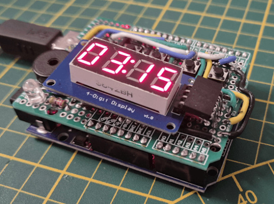
Eine Eieruhr mit Arduino? Warum nicht! In diesem Projekt baue ich eine digitale Countdown-Uhr, die die verbleibende Zeit auf einer 4-stelligen 7-Segment-Anzeige darstellt und nach Ablauf ein akustisches Signal über einen Piezo-Buzzer ausgibt. https://youtu.be/Sn4FxH1B3s4 Ein besonderer Vorteil dieser Anzeige ist, dass sie einen Doppelpunkt besitzt. Dadurch kann die Zeitdarstellung automatisch angepasst werden: - Bis 59 Sekunden wird der Countdown klassisch in Sekunden angezeigt. - Ab 60 Sekunden wechselt die Anzeige in das MM:SS-Format (Minuten:Sekunden). Dadurch ist eine maximale Countdown-Zeit von 99 Minuten und 59 Sekunden möglich – perfekt für das Frühstücksei, aber auch ideal für längere Koch- oder Backvorgänge. Die Steuerung erfolgt über zwei Taster: 🔴 Roter Taster – Stoppt den Timer jederzeit. 🟢 Grüner Taster – Startet den Timer mit der voreingestellten Zeit. Das Ganze läuft auf einem Arduino Nano V3, der genauso leistungsfähig wie ein Arduino UNO ist, aber deutlich kompakter. Im folgenden Abschnitt zeige ich dir, wie du diese digitale Eieruhr mit flexibler Zeitdarstellung und akustischem Countdown-Signal ganz einfach selbst nachbauen kannst!

Schaltung - Arduino Eieruhr Hinweis: Idee aus der Community - Die Idee zu diesem Beitrag stammt von einem Leser meines Blogs, der sich zum Beitrag „Flexibler Timer für Arduino: Wie du die Zeit per Poti regulierst“ gemeldet hat. Dort habe ich gezeigt, wie man mit einem Drehpotentiometer die Timersteuerung am Arduino flexibel anpassen kann.

Schaltung - Arduino UNO R4 Minima - Drehpotentiometer und LEDs

Schaltung - Arduino UNO R4 Minima mit Servomotor SG90 und Drehpotentiometer Zunächst habe ich versucht, die Zeitsteuerung mit einem Rotary Encoder zu realisieren. Allerdings führte das Aktualisieren der 4-stelligen 7-Segmentanzeige dazu, dass Impulse des Encoders nicht zuverlässig erkannt wurden. Deshalb bin ich auf eine einfache und robuste Lösung mit drei Tastern umgestiegen: - „+“ erhöht den Timer-Wert. - „-“ verringert den Timer-Wert. - „Select“ wechselt zwischen Minuten- und Sekunden-Einstellung. Diese Lösung ist nicht nur stabiler, sondern auch intuitiv in der Bedienung. Ich freue mich immer über Input aus der Community und helfe gerne weiter, wenn es um spannende Projekte geht. Falls du also eigene Ideen oder Fragen hast, hinterlasse einfach einen Kommentar – vielleicht wird daraus ja der nächste Blogbeitrag! 😊
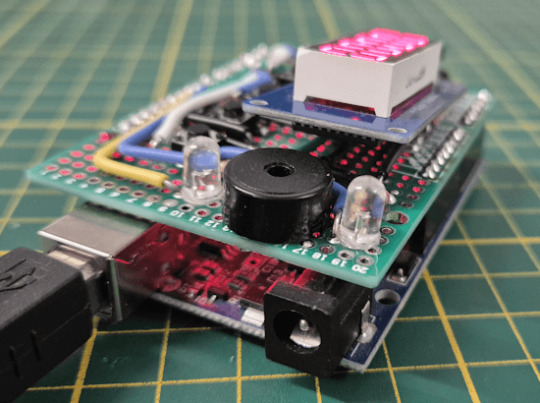
Aufbau der Schaltung - Eieruhr mit Segmentanzeige und Taster am Arduino Nano
Bevor wir die Schaltung auf eine Platine übertragen, bauen wir sie zunächst auf einem Breadboard auf. Dafür benötigen wir folgende Komponenten: - Arduino Nano V3* (inkl. Datenkabel) - Piezo-Buzzer* für das akustische Signal - fünf Taster mit Tasterkappen* (Start/Stopp) - 4-stellige 7-Segmentanzeige Typ TM1637* - 830-Pin Breadboard* für den Hauptaufbau - 170-Pin Breadboard* für die Segmentanzeige - diverse Breadboardkabel* zur Verkabelung Hinweis von mir: Die mit einem Sternchen (*) markierten Links sind Affiliate-Links. Wenn du über diese Links einkaufst, erhalte ich eine kleine Provision, die dazu beiträgt, diesen Blog zu unterstützen. Der Preis für dich bleibt dabei unverändert. Vielen Dank für deine Unterstützung! Falls du keinen Arduino Nano V3 zur Hand hast, kannst du alternativ auch ein Arduino UNO oder Arduino Mega verwenden. Ich habe mich für den Nano entschieden, da er genauso leistungsfähig wie der UNO ist, aber deutlich kompakter – was später für die endgültige Schaltung von Vorteil ist.

Schaltung - Arduino mit Taster - Segmentdisplay und Piezo Buzzer Wenn du es aber noch kompakter als den schon kleinen Arduino Nano V3 haben möchtest, dann kannst du den Super Mini Arduino Nano Clone verwenden welchen ich im Beitrag Arduino Nano Clone von Aliexpress: Günstig, aber oft mit Mängeln vorgestellt habe. Dieser bietet trotz seiner Größe genügend Pins & Power für dieses Projekt.

Alternativer Aufbau am Arduino UNO R3/R4 mit Prototyp-Board
Die Schaltung ist kompakt genug um auch auf einem Prototyp-Board für den Arduino UNO gebaut zu werden.

Da der neue Arduino UNO R4 das selbe Pinout hat wie der Vorgänger UBO R3 kannst du hier auch auf den neuen Mikrocontroller der Arduino Familie setzen.
Programmieren der Arduino Eieruhr in der Arduino IDE
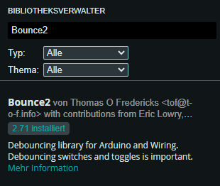
Wie du einen Taster, Drehpotentiometer, Piezo Buzzer und auch die 4fach 7 Segmentanzeige am Arduino programmierst habe ich dir bereits in separaten Beiträgen gezeigt. - Arduino Lektion 87: Taster entprellen - Arduino UNO R3 – Gabellichtschranke& Piezo Buzzer - Arduino Lektion 26: TM1637 – 4 Digit 7 Segment Display Nachfolgend, die Schritt-für-Schritt-Anleitung zur erstellung des Sketches für die Eieruhr. Schritt 1 - einbinden der benötigten Module Für die Ansteuerung der 4fach 7 Segmentanzeige vom Typ TM1637 und zum entprellen der Taster benötigen wir jeweils eine Bibliothek. Diese können wir über den Bibliotheksverwalter installieren.
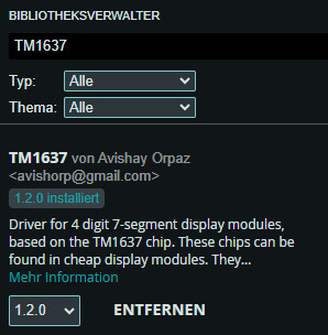
Sobald beide Bibliotheken installiert sind, können wir sie mit dem folgenden Befehl in unser Projekt einbinden. #include // Bibliothek für die 7-Segment-Anzeige (TM1637) #include // Bibliothek zur Tasten-Entprellung Schritt 2 - definieren der verwendeten Pins & Objekte initialisieren Im nächsten Schritt definieren wir die Pins für die verbauten Komponenten und initalisieren die entsprechenden Objekte. // Pins für die 7-Segment-Anzeige #define segmentanzeige_CLK 6 #define segmentanzeige_DIO 5 TM1637Display display(segmentanzeige_CLK, segmentanzeige_DIO); // Anzeige-Objekt erstellen // Tasten-Pins definieren #define tasterStopp 3 #define tasterStart 4 #define tasterPlus 7 #define tasterMinus 8 #define tasterSelect 9 // Bounce-Objekte für die Tasten-Entprellung Bounce bceTasterStopp = Bounce(); Bounce bceTasterStart = Bounce(); Bounce bceTasterPlus = Bounce(); Bounce bceTasterMinus = Bounce(); Bounce bceTasterSelect = Bounce(); // Pin für den Piezo-Buzzer #define buzzer 10 Schritt 3 - Felder zum speichern der Zustände Für unseren Code benötigen wir einpaar Felder in welche wir zbsp. speichern ob der Countdown gerade läuft und wie hoch der Countdown ist. // Variable für den Countdown in Sekunden unsigned int seconds = 0; // Timer-Zustand (läuft oder gestoppt) bool clockStarted = false; // Auswahl der Zeiteinheit: // 0 = Sekunden, 1 = Minuten unsigned int timeAuswahl = 0; // Wartezeit zwischen Sekundenverringerungen const unsigned int PAUSE = 1000; unsigned long lastAction = 1L; // Alarmzustand (true = abgelaufen) bool alarm = false; Schritt 4 - Funktion Setup Die setup()-Funktion wird einmalig beim Start des Mikrocontrollers aufgerufen – sowie nach einem Neustart über den RESET-Taster. In dieser Funktion legen wir die Helligkeit der 7-Segment-Anzeige fest und verknüpfen die Taster-Pins mit den Bounce-Objekten, um eine zuverlässige Tastenentprellung zu gewährleisten. void setup() { Serial.begin(9600); Serial.println("Initialized"); // Debug-Ausgabe // Helligkeit der 7-Segment-Anzeige setzen (maximale Helligkeit: 7) display.setBrightness(7); // Anzeige initial mit "--:--" belegen uint8_t data = { 0xff, 0xff, 0xff, 0xff }; display.setSegments(data); // Taster als Eingänge mit Pull-Up-Widerständen definieren und entprellen bceTasterStopp.attach(tasterStopp, INPUT_PULLUP); bceTasterStopp.interval(5); bceTasterStart.attach(tasterStart, INPUT_PULLUP); bceTasterStart.interval(5); bceTasterPlus.attach(tasterPlus, INPUT_PULLUP); bceTasterPlus.interval(5); bceTasterMinus.attach(tasterMinus, INPUT_PULLUP); bceTasterMinus.interval(5); bceTasterSelect.attach(tasterSelect, INPUT_PULLUP); bceTasterSelect.interval(5); pinMode(buzzer, OUTPUT); // Buzzer als Ausgang setzen displayTime(); // Anfangszeit auf dem Display aktualisieren } Schritt 5 - Funktion loop Die loop()-Funktion wird kontinuierlich ausgeführt und enthält den Code für die Steuerung der Eieruhr. Bevor wir die Taster auswerten können, müssen wir sie mit der Funktion update() aktualisieren. Anschließend können wir mit fell() überprüfen, ob ein Taster losgelassen wurde, um entsprechende Aktionen auszuführen. // Tasten aktualisieren (Entprellung) bceTasterStopp.update(); bceTasterStart.update(); // Taster "Stopp" beendet den Timer und setzt den Alarm zurück if (bceTasterStopp.fell()) { clockStarted = false; alarm = false; } // Taster "Start" beginnt den Countdown if (bceTasterStart.fell()) { clockStarted = true; alarm = false; } Der Countdown wird durch das Drücken der Start-Taste aktiviert, wodurch die Variable clockStarted auf true und alarm auf false gesetzt wird. Dadurch beginnt der Timer zu laufen und zählt in der loop()-Funktion in Schritten von einer Sekunde herunter. // Wenn der Timer läuft und noch nicht abgelaufen ist else if (clockStarted && !alarm) { unsigned long currentMillis = millis(); // Jede Sekunde die Zeit verringern if ((lastAction + PAUSE) lastAction = currentMillis; if (seconds > 0) { seconds--; // Eine Sekunde abziehen } else { alarm = true; // Timer abgelaufen } } displayTime(); Solange der Countdown nicht gestartet ist, also die Variable clockStarted auf false steht, kann die Zeit eingestellt werden. Über die Select-Taste lässt sich zwischen den beiden Einstellfeldern Minuten und Sekunden wechseln. - In der Sekunden-Einstellung wird der Wert sekundengenau um eins erhöht oder verringert. - Ist die Minuten-Einstellung aktiv, werden 60 Sekunden zur Variable seconds hinzugefügt oder abgezogen. if (!clockStarted) { bool buttonPressed = false; // Taster "Select" wechselt zwischen Minuten- und Sekundenmodus if (bceTasterSelect.fell()) { timeAuswahl = (timeAuswahl == 0) ? 1 : 0; } // Taster "+" erhöht die Sekunden oder Minuten if (bceTasterPlus.fell()) { buttonPressed = true; if (timeAuswahl == 0) { seconds++; } else { seconds += 60; } } // Taster "-" verringert die Sekunden oder Minuten if (bceTasterMinus.fell() && seconds > 0) { buttonPressed = true; if (timeAuswahl == 0) { seconds--; } else { seconds -= 60; } } // Nach einer Änderung die neue Zeit anzeigen if (buttonPressed) { displayTime(); } }
fertiger Quellcode - Arduino Eieruhr mit flexiblem Timer
Nachfolgende der fertige Code mit Kommentaren etc. /* Arduino-gestützte Eieruhr: Flexible Countdown-Anzeige mit akustischem Alarm Dieses Programm steuert eine digitale Eieruhr mit einem Arduino Nano V3. Der Countdown wird auf einer 4-stelligen TM1637 7-Segmentanzeige dargestellt. Die Bedienung erfolgt über drei Taster: - "+" und "-" zur Zeiteinstellung - "Select" zum Wechsel zwischen Minuten- und Sekundeneinstellung - "Start" und "Stopp" zur Steuerung des Timers Nach Ablauf der eingestellten Zeit gibt ein Piezo-Buzzer ein akustisches Signal aus. Weitere Informationen und die vollständige Anleitung findest du hier: https://draeger-it.blog/arduino-gestuetzte-eieruhr-flexible-countdown-anzeige-mit-akustischem-alarm/ Author: Stefan Draeger Webseite: https://draeger-it.blog Kontakt: [email protected] */ #include // Bibliothek für die 7-Segment-Anzeige (TM1637) #include // Bibliothek zur Tasten-Entprellung // Pins für die 7-Segment-Anzeige #define segmentanzeige_CLK 6 #define segmentanzeige_DIO 5 TM1637Display display(segmentanzeige_CLK, segmentanzeige_DIO); // Anzeige-Objekt erstellen // Tasten-Pins definieren #define tasterStopp 3 #define tasterStart 4 #define tasterPlus 7 #define tasterMinus 8 #define tasterSelect 9 // Bounce-Objekte für die Tasten-Entprellung Bounce bceTasterStopp = Bounce(); Bounce bceTasterStart = Bounce(); Bounce bceTasterPlus = Bounce(); Bounce bceTasterMinus = Bounce(); Bounce bceTasterSelect = Bounce(); // Pin für den Piezo-Buzzer #define buzzer 10 // Variable für den Countdown in Sekunden unsigned int seconds = 0; // Timer-Zustand (läuft oder gestoppt) bool clockStarted = false; // Auswahl der Zeiteinheit: // 0 = Sekunden, 1 = Minuten unsigned int timeAuswahl = 0; // Wartezeit zwischen Sekundenverringerungen const unsigned int PAUSE = 1000; unsigned long lastAction = 1L; // Alarmzustand (true = abgelaufen) bool alarm = false; void setup() { Serial.begin(9600); Serial.println("Initialized"); // Debug-Ausgabe // Helligkeit der 7-Segment-Anzeige setzen (maximale Helligkeit: 7) display.setBrightness(7); // Anzeige initial mit "--:--" belegen uint8_t data = { 0xff, 0xff, 0xff, 0xff }; display.setSegments(data); // Taster als Eingänge mit Pull-Up-Widerständen definieren und entprellen bceTasterStopp.attach(tasterStopp, INPUT_PULLUP); bceTasterStopp.interval(5); bceTasterStart.attach(tasterStart, INPUT_PULLUP); bceTasterStart.interval(5); bceTasterPlus.attach(tasterPlus, INPUT_PULLUP); bceTasterPlus.interval(5); bceTasterMinus.attach(tasterMinus, INPUT_PULLUP); bceTasterMinus.interval(5); bceTasterSelect.attach(tasterSelect, INPUT_PULLUP); bceTasterSelect.interval(5); pinMode(buzzer, OUTPUT); // Buzzer als Ausgang setzen displayTime(); // Anfangszeit auf dem Display aktualisieren } // Funktion zur Anzeige der aktuellen Zeit auf dem 7-Segment-Display void displayTime() { int minutes = seconds / 60; // Minuten berechnen // Begrenzung auf maximal 99 Minuten if (minutes > 99) { minutes = 99; } int fourDigitValue = (minutes * 100) + (seconds % 60); // Anzeigeformat MM:SS display.showNumberDecEx(fourDigitValue, 0b01000000, true, 4, 4); } void loop() { // Tasten aktualisieren (Entprellung) bceTasterStopp.update(); bceTasterStart.update(); bceTasterPlus.update(); bceTasterMinus.update(); bceTasterSelect.update(); // Wenn die Uhr nicht läuft, kann die Zeit eingestellt werden if (!clockStarted) { bool buttonPressed = false; // Taster "Select" wechselt zwischen Minuten- und Sekundenmodus if (bceTasterSelect.fell()) { timeAuswahl = (timeAuswahl == 0) ? Read the full article
0 notes
Text
La Domotica di un frontaliere ventimigliese
La Domotica di un frontaliere ventimigliese https://ift.tt/DGzglb1 Fonte: Flavio Palermo Da parecchi anni faccio esperienze con IoT. L'Internet of Things (IoT) è una rete di oggetti e dispositivi connessi (detti “cose”), dotati di sensori (e altre tecnologie), che consentono loro di trasmettere e ricevere dati, da e verso altre cose e sistemi. Oggi l'IoT è ampiamente utilizzato in ambito industriale (IIoT) ed è sinonimo di Industry 4.0. L'impianto elettrico elettronico del mio appartamento è gestito appunto dall'IoT con un Arduino MEGA nel quadro elettrico ed Home Assistant. Home Assistant, software open-source in grado di controllare tutti i dispositivi Smart all'interno di un'abitazione, dalle luci, ai condizionatori, alle automazioni per le tapparelle. Installato su un Raspberry 4 pi 8Gb ssd 250Gb. Al di là dei tecnicismi, Raspberry Pi può essere considerato un “computer in miniatura”, un intero ecosistema hardware raccolto in un’unica board. Nasce in Inghilterra per favorire la diffusione della programmazione e della cultura informatica, ma il suo incredibile successo ne ha svelato miriadi di altri utilizzi. Considerando la motivazione primaria, appare assolutamente adeguato il motto che campeggia sulla homepage del progetto: “Our mission is to put the power of computing and digital making into the hands of people all over the world” (“La nostra missione consiste nel mettere il potere della programmazione e della creazione digitale nelle mani di persone di ogni parte del mondo”). Questa frase è una sintesi perfetta per raccontare uno strumento che ha favorito il fiorire della creatività nel mondo senza limitazioni politiche, sociali o economiche: strada poi percorsa da BBC micro:bit, altro prodotto inglese. L'impianto elettrico elettronico del mio appartamento è gestito appunto dall'IoT con un Arduino MEGA nel quadro elettrico ed Home Assistant". Arduino è una piattaforma hardware composta da una serie di schede elettroniche dotate di un microcontrollore. È stata ideata e sviluppata nel 2005 da alcuni membri dell'Interaction Design Institute di Ivrea come strumento per la prototipazione rapida e per scopi hobbistici, didattici e professionali. Poi ad un certo punto ho spento tutto e ti spiego il perché. Agosto 2022: acquisto un misuratore di energia che installo nel quadro elettrico. Ed effettivamente mi rendo conto che in mia assenza avevo un consumo di ben 300Watt a vuoto e una bolletta bimestrale di 275 euri. Modem Nas, videosorveglianza, allarme, tutti i dispositivi IoT ecc. Ecc. Accesi che magari mi collegavo 10 minuti al giorno da Monaco. Quindi ho deciso di spegnere tutto per fare una prova abbassando il consumo da 300W a 5W. Bolletta? Da 275 a 55 euro 1/5. Be', visti i risultati, è da agosto 2022 che quando esco di casa si spegne in automatico. Dovrei brevettare il progetto: ECOMOTICA... Flavio Palermo, 31 luglio 2024 Fonte: Flavio Palermo Non sono in grado di affermare se il termine "Domotica" si applichi al meglio alle situazioni descritte qui da Flavio Palermo, ma all'epoca dei suoi primi esperimenti telematici - che circa trent'anni fa cercò di farmi capire la parola era molto diffusa (e densa di aspettative che non so in realtà quanto si siano verificate) - in circoscritti ambiti del mio lavoro, così che mi piace usarla, al confine tra una citazione e l'autoironia. Adriano Maini via Aspetti rivieraschi https://ift.tt/zOZvkoL August 05, 2024 at 08:12AM
0 notes
Text
Arduino Programming for Beginners: A Step-by-Step Guide
In the world of electronics and robotics, Arduino programming for beginners serves as an essential starting point for those eager to dive into the realm of microcontrollers and embedded systems. Arduino is an open-source platform that combines hardware and software, making it an ideal choice for newcomers. At Technobotics, we understand the importance of accessible and comprehensive learning resources for budding tech enthusiasts. This guide aims to provide a clear and straightforward introduction to Arduino programming for beginners.
What is Arduino?

Arduino is a microcontroller-based platform that allows users to create interactive electronic projects. The platform includes a programmable circuit board (microcontroller) and a software IDE (Integrated Development Environment) for writing and uploading code to the hardware. Arduino boards come in various models, such as the Arduino Uno, Arduino Mega, and Arduino Nano, each catering to different project requirements.
Getting Started with Arduino

1. Gather Your Components
To begin Arduino programming for beginners, you will need the following components:
An Arduino board (Arduino Uno is recommended for beginners)
USB cable to connect the Arduino to your computer
A computer with the Arduino IDE installed
Basic electronic components like LEDs, resistors, and breadboards
2. Install the Arduino IDE
The Arduino IDE is the software used to write and upload code to the Arduino board. It is available for Windows, macOS, and Linux. You can download it from the official Arduino website. Once downloaded, follow the installation instructions specific to your operating system.
3. Connect Your Arduino
Use the USB cable to connect your Arduino board to your computer. The power LED on the board should light up, indicating that the board is receiving power. Open the Arduino IDE and select the correct board and port from the 'Tools' menu.
4. Write Your First Program
In Arduino programming for beginners, the first program you usually write is the "Blink" program, which makes an LED blink on and off. Open the Arduino IDE, and you will see a blank sketch (a program written in the Arduino language).
Here is the "Blink" code:// the setup function runs once when you press reset or power the board void setup() { // initialize digital pin LED_BUILTIN as an output. pinMode(LED_BUILTIN, OUTPUT); }
// the loop function runs over and over again forever void loop() { digitalWrite(LED_BUILTIN, HIGH); // turn the LED on (HIGH is the voltage level) delay(1000); // wait for a second digitalWrite(LED_BUILTIN, LOW); // turn the LED off by making the voltage LOW delay(1000); // wait for a second }
5. Upload the Code
Click the 'Upload' button in the Arduino IDE to upload the code to your Arduino board. The onboard LED should start blinking, indicating that the code has been successfully uploaded and is running on the board.
Understanding the Code

In Arduino programming for beginners, understanding the basic structure of an Arduino sketch is crucial.
setup() function: This function runs once when the board is powered on or reset. It is used to initialize variables, pin modes, start using libraries, etc.
loop() function: This function runs continuously after the setup() function has completed. It is where the main logic of the program resides.
In the "Blink" example:
pinMode(LED_BUILTIN, OUTPUT); sets the LED pin as an output.
digitalWrite(LED_BUILTIN, HIGH); turns the LED on.
delay(1000); pauses the program for one second.
digitalWrite(LED_BUILTIN, LOW); turns the LED off.
delay(1000); pauses the program for another second.
Exploring More Projects

Once you are comfortable with the basics of Arduino advanced programming, you can explore more complex projects. Here are a few ideas to get you started:
1. Temperature and Humidity Monitor
Use a DHT11 sensor to measure temperature and humidity. Display the readings on an LCD screen. This project introduces you to using sensors and displaying data.
2. Motion Detector
Create a motion detector using a PIR sensor and an LED. When motion is detected, the LED will light up. This project helps you understand how to use sensors to trigger actions.
3. Servo Motor Control
Learn to control a servo motor using a potentiometer. This project is excellent for understanding how to read analog input and control output devices.
Troubleshooting Tips

As you delve into Arduino programming courses for beginners, you might encounter some common issues. Here are a few troubleshooting tips:
Board Not Recognized: Ensure the correct board and port are selected in the Arduino IDE.
Code Not Uploading: Check your USB connection and ensure no other program is using the same COM port.
LED Not Blinking: Double-check your code for errors and ensure the correct pin is being used.
Conclusion
Arduino programming for beginners is a rewarding journey that opens up endless possibilities for creating interactive electronic projects. At Technobotics, we are committed to providing you with the resources and support you need to succeed. Start small, experiment, and gradually take on more complex projects. Happy tinkering!
By following this guide, you will be well on your way to mastering the basics of Arduino programming and ready to explore the exciting world of electronics and robotics. For more tutorials and resources, visit our website and join our community of tech enthusiasts.
#robotics courses for kids#arduino advanced programming courses#arduino courses in mumbai#arduino programming courses#arduino programming for beginners
0 notes
Text

L298N Motor Driver Module 2A
This L298N Motor Driver Module is a high power motor driver perfect for driving DC Motors and Stepper Motors. It uses the popular L298N motor driver IC and has the onboard 5V regulator which it can supply to an external circuit. It can control up to 4 DC motors, or 2 DC motors with directional and speed control This motor driver is perfect for robotics and mechatronics projects and perfect for controlling motors from microcontrollers, switches, relays, etc. Perfect for driving DC and Stepper motors for micro mouse, line-following robots, robot arms, etc.
Note: It is recommended to buy a good quality version of this product. You can buy it by clicking here: L298N Motor Driver Module – Good Quality. The reason is that the good quality version product has a better quality of components as compared to standard ones.
Pins:
Out1:Motor A lead out
Out2:Motor A lead out
Out3:Motor B lead out
Out4:Mo (Can actually be from 5v-35v, just marked as 12v)
GND :Ground
5v :5v input (unnecessary if your power source is 7v-35v, if the power source is 7v-35v then it can act as a 5v out)
EnA :Enables PWM signal for Motor A (Please see the “Arduino Sketch Considerations†section)
In1 :Enable Motor A
In2 :Enable Motor A
In3 :Enable Motor B
In4 :Enable Motor B
EnB :Enables PWM signal for Motor B (Please see the “Arduino Sketch Considerations†section)
Usage: H-bridges are typically used in controlling motors speed and direction but can be used for other projects such as driving the brightness of certain lighting projects such as high powered LED arrays.
Two things to mention: Make sure you have all of your grounds tied together; Arduino, Power source, and the Motor Controller. The PWM Pins are unnecessary if you do not want to control PWM features.
Arduino Sketch Considerations: The Arduino code sketch is pretty straightforward. Since there isn’t a library for the L298N Dual H-Bridge Motor Controller you just have to declare which pins the controller is hooked to. The “int dir(number)Pin(letter) pins can be connected to any available digital pin you have available, as long as you declare the correct pin in your sketch. This makes the L298N Dual H-Bridge Motor Controller very versatile if your project is using a lot of Arduino pins. The int“speeding(letter)†pins need to be connected to a PWM pin on the Arduino if you want to enable speed control through PWM. As a quick cheat I have included a list of PWM pins for the main two types of Arduino I use: AT MEGA PWM: 2 to 13 and 44 to 46. Provide 8-bit PWM output with the analogWrite() function. UNO PWM: 3, 5, 6, 9, 10, and 11. Provide 8-bit PWM output with the analogWrite() function. Note: Built-in 5v power supply, when the driving voltage is 7v-35v
Features: -Current Sense for each motor. -Heatsink for better performance. -Power-On LED indicator. -Drives up to 4 motors.
0 notes

Text
Arduino Projects
The Arduino platform, which is based on microcontrollers, makes it easier to create and execute electronic projects. A physical programmable circuit board serves as the hardware component, and an Integrated Development Environment, or IDE, is the software that is used to write and upload code to the board. You can select the board that best fits your project requirements from a range of options, including Arduino Uno, Mega, and Nano.
Top Arduino Projects to Try
Automation System for Smart Homes
Use an automation system driven by Arduino to turn your house into a smart home. Voice commands or your smartphone can be used to operate lights, fans, and other appliances. You may increase the efficiency and intelligence of your house by incorporating sensors and modules like the ESP8266 Wi-Fi module or the HC-05 Bluetooth module.
The weather station
To keep an eye on the temperature, humidity, and air pressure, build your own weather station. In addition to improving your knowledge of sensors, this project offers real-time data collecting, which may be helpful for practical or instructional reasons.
Line-Following Robot
An excellent project to start learning robotics is a line-following robot. The robot detects and follows a predetermined course using infrared sensors. The fundamentals of sensor integration and motor control are covered in this project.
Arduino-Based LED Cube
Programming patterns and animations into a 3D matrix of LEDs creates the visually beautiful LED cube. This project is ideal for teaching 3D coordinate systems and multiplexing.
Smart Plant Watering System
A smart watering system that employs soil moisture sensors to water your plants automatically when necessary will help you keep them healthy. For people who travel regularly or are busy, this project is ideal.
Gesture-Controlled Robot
Create a robot that can be directed by gestures to advance robotics. Simple hand gestures can be used to control the robot's motions utilizing an accelerometer and two Arduino boards.
Arduino projects are a great way to realize your imaginative ideas and gain useful programming and electronics skills. Whether you're a professional, student, or enthusiast, Arduino offers countless opportunities. Use this strong and flexible platform to dive in, try things out, and see your ideas come to life!
To know more, click here.
0 notes